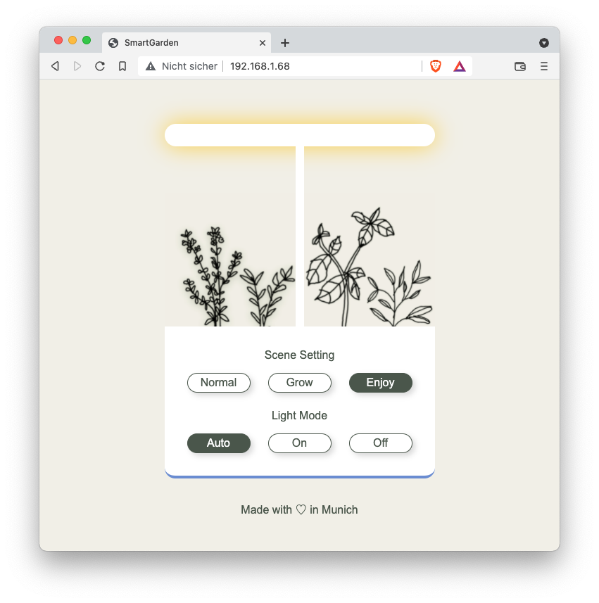
IDOO’s hydroponic systems are great for growing plants inside. They are controlled using on-device buttons. In this project, I replaced all circuit boards with an ESP8266 microcontroller plus some additional electronics to control LEDs and pump. This allows for remote control via a web UI and custom LED and pump settings. In addition, this project could easily be extended using sensors, for example to check water or nutrition levels.
Find all details on GitHub.
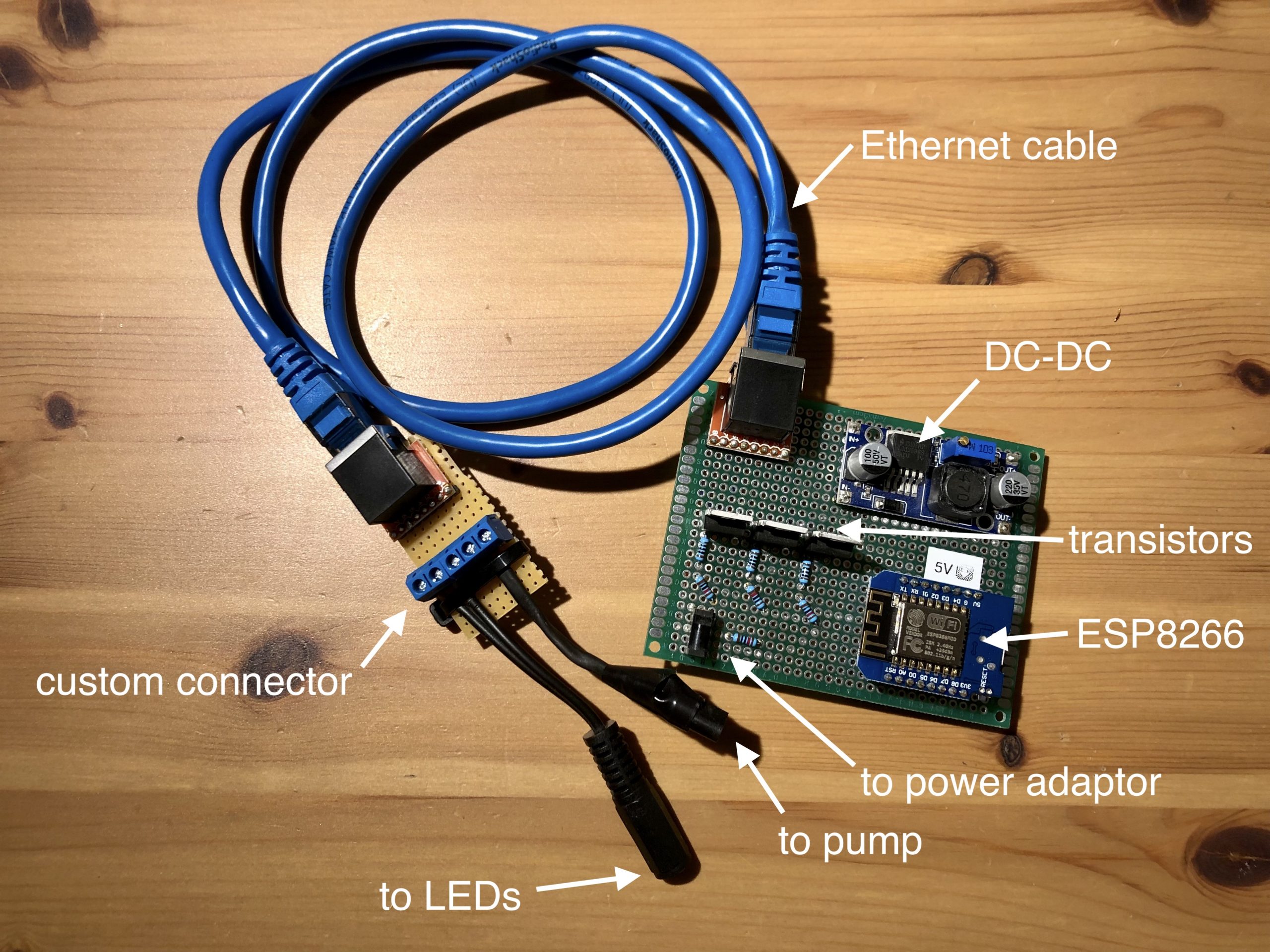
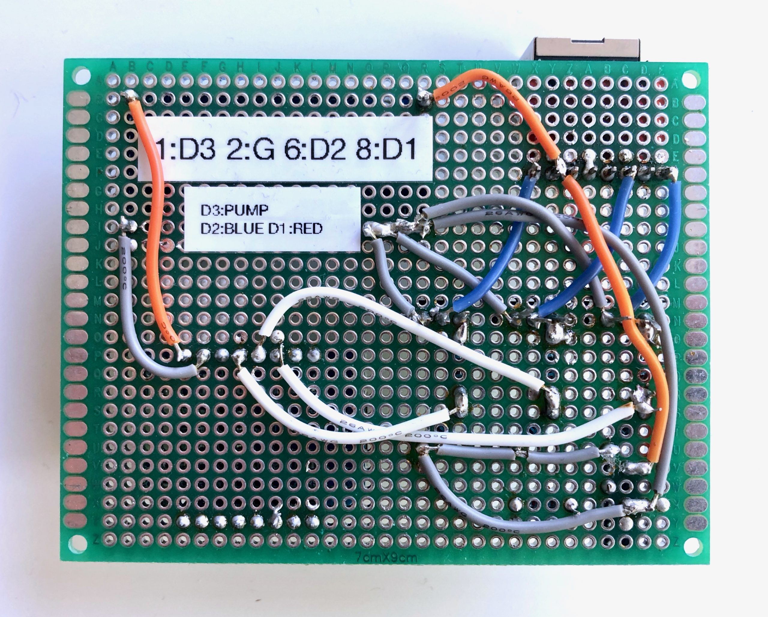
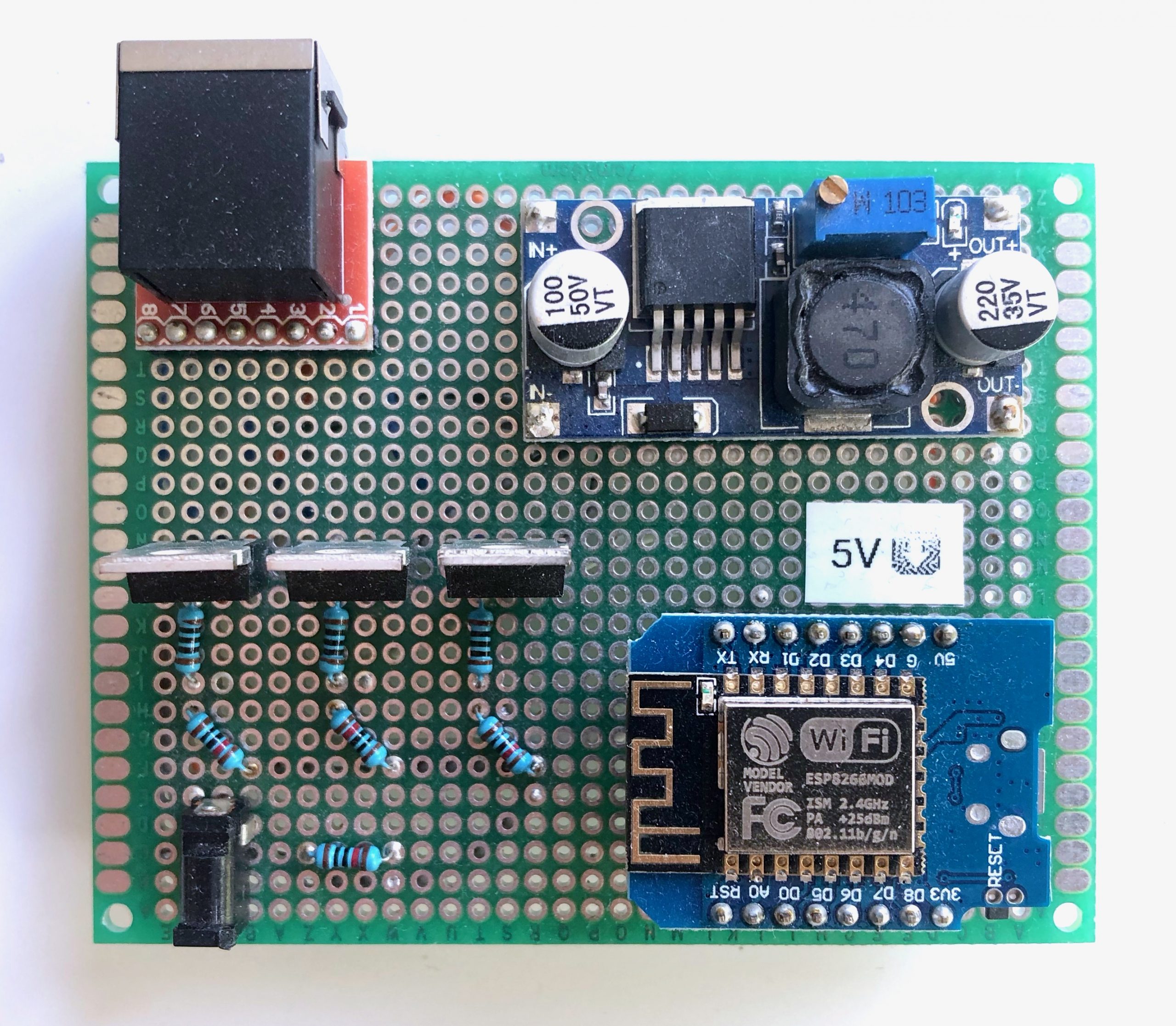
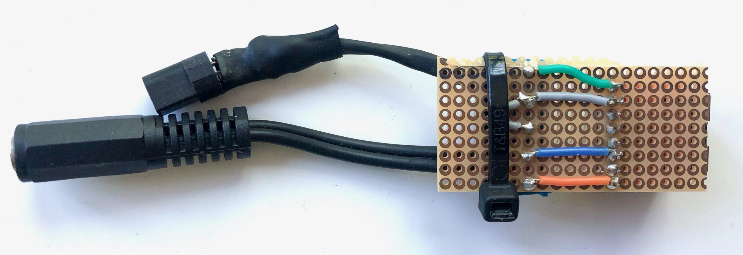
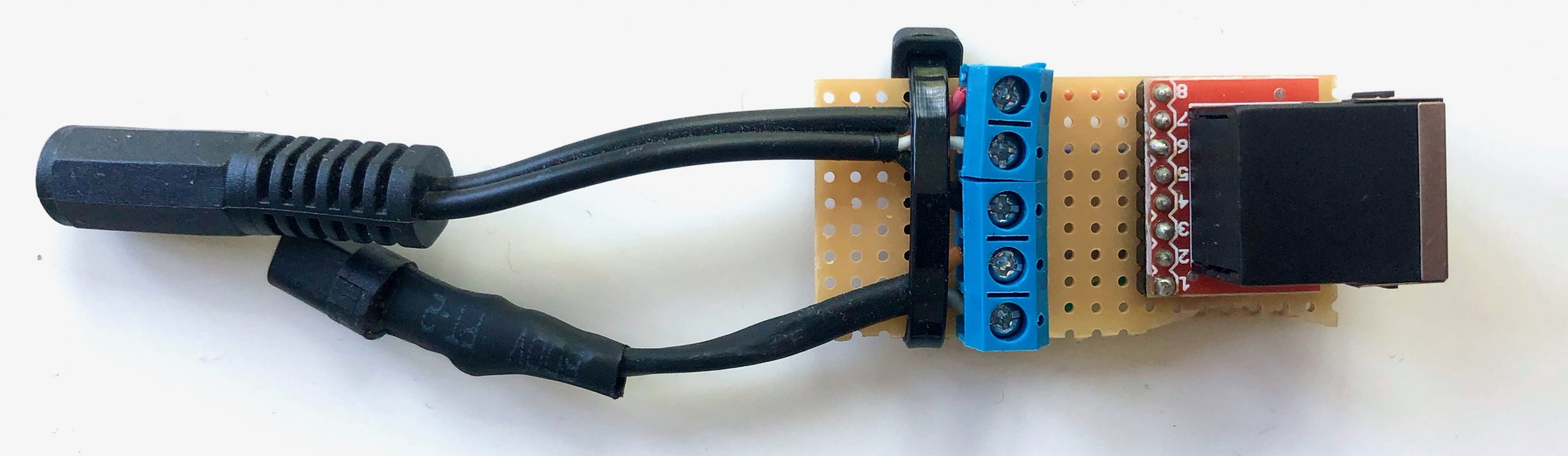
Circuit Detail Pictures
Hey, we recently ran into the same problem with our IDOO circuit board with water damage. We are trying to look for a way to replace it and stumbled upon your solution w the Arduino. Do you have a list of the specific hardware components, like transistors, resistors, any other components, and maybe a circuit diagram of the connections? Trying to replicate your solution, but have a bit less experience than you do with ICs it seems.
Hey Zack, sorry to hear about the water damage. And thanks for your interest in the project! At the time, I did not create a components list or circuit diagram, unfortunately. But looking at the board, this should cover the main components:
* 3x IRLZ 44N MOSFET
* 3x 100Ω resistors
* 3x 1kΩ resistors
* 1x DC-DC converter (in case you want to power the Arduino via the 24v IDOO AC adapter)
I followed the circuit described here: https://forum.arduino.cc/t/leds-dimmen-pwm/893221/16 (without the diode, anyway marked as optional). You would have to build this circuit three times: 1 for the pump, and 1 for each of the 2 LED colors. Hope this helps!
Hi Dominik, I would like to replicate your system to control the smart garden from app.
Could you please share a picture of the connection circuit?
I have bought all the components, but I am a beginner, any help is appreciated
Hi Nicola, thanks for your interest and question! I added some detail pictures of the circuits to the post. I hope this helps! I followed the circuit described here: https://forum.arduino.cc/t/leds-dimmen-pwm/893221/16 (without the diode), but did not make a diagram of my complete circuit when building it.
Note: I also updated the connector slightly now, using an Ethernet cable and sockets instead of the hardwired connection. The functionality stays the same, though, it’s just a bit more convenient when using.
Really nice article, I have a Idoo 12 plat with no app control , I shall try this!
Good work!
Have just ordered some components at Temu.
Thank you! Let me know how it goes.